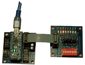
Arduino Nano + Board 0101v4 + Board 0104v3 : 
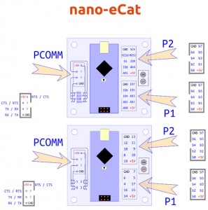
nano-eCat pinout :
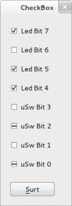
pyQt + pyFirmata custom program :
This layout is designed with Qt Designer : led_uSw.ui
(pyuic4 led_uSw.ui > ui_led_uSw.py)
It can be converted in Python : ui_led_uSw.py
Code to use nano-eCat’s P2 : exFirmata03.py
Code to use nano-eCat’s P1 : exFirmata03P1.py
Using digital outputs :
#self.ledB7 = 13 # P2b7
#self.ledB6 = 12 # P2b6
#self.ledB5 = 11 # P2b5
#self.ledB4 = 10 # P2b4
self.ledB7 = 7 # P1b7
self.ledB6 = 6 # P1b6
self.ledB5 = 5 # P1b5
self.ledB4 = 4 # P1b4
self.board.digital[self.ledB4].write(state)
Using digital inputs :
self.uSwB3 = 9 # P2b3
self.uSwB2 = 8 # P2b2
self.cfgB3 = ‘d:’ + str(self.uSwB3) + ‘:i’
self.cfgB2 = ‘d:’ + str(self.uSwB2) + ‘:i’
self.board.get_pin(self.cfgB3)
self.board.get_pin(self.cfgB2)
self.board.digital[self.uSwB3].enable_reporting()
self.board.digital[self.uSwB2].enable_reporting()
state = self.board.digital[self.uSwB3].read()
Using analog inputs as digital inputs :
Nowadays, analog pins (AD0-AD5) can’t be used directly as digital inputs in standard Firmata. A solution for this inconvenience could be :
if (self.board.analog[self.uSwB0].read() > 0.5) :
Using analog inputs changes numbering policy :
#self.uSwB1 = 18 # P2b1
#self.uSwB0 = 19 # P2b0
#self.uSwB1 = 4 # P2b1 as analog
#self.uSwB0 = 5 # P2b0 as analog
#self.uSwB3 = 17 # P1b3
#self.uSwB2 = 16 # P1b2
#self.uSwB1 = 15 # P1b1
#self.uSwB0 = 14 # P1b0
self.uSwB3 = 3 # P1b3 as analog
self.uSwB2 = 2 # P1b2 as analog
self.uSwB1 = 1 # P1b1 as analog
self.uSwB0 = 0 # P1b0 as analog
And they should be declared as analog inputs :
self.cfgB1 = ‘a:’ + str(self.uSwB1) + ‘:i’
self.cfgB0 = ‘a:’ + str(self.uSwB0) + ‘:i’
self.board.get_pin(self.cfgB1)
self.board.get_pin(self.cfgB0)
self.board.analog[self.uSwB1].enable_reporting()
self.board.analog[self.uSwB0].enable_reporting()

